
AURORA BOREALIS IN A VODKA BOTTLE
Ambiance light with an LDR switch
NORTHERN LIGHTS IN LAPPLAND | |
|
The last time I saw the Aurora Borealis phenomenom, I was traveling in the Geavu Wastelands of Northern Lappland in december 2013. I was in quite sad moods that time due to being left by the most loved one. I was in a need of some dangerous adventure.
My travel companion was sitting in the driver's place, when we speeded towards Nuorgam, the Northernmost location of Finland. It was almost midnight and outside temperature was decrasing into 25 degrees subzero. I saw some faint clouds in the black night sky. Soon after I realized that there shouldn't be seen any kind of clouds, because it was pitch-dark outside. I asked my comapanion to stop by the next truck resting place. Saddly the next truck stop was unploughed and my friend unexpectedly crashed my rental car deep into a snow bank.
I had a plenty of time to watch the Northern lights, before an ukranian tourist convoy stopped to help us out.
NORTHERN LIGHTS IN A VODKA BOTTLEIn June 2014 I was studying guitar distortion effects, when I tumbled into a Finnish site dealing with leisure electronic researches (Harraste-elektroniikka). There I saw a project named LED Finlandia, where the builder had assembled LEDs inside a decorative Vodka bottle. Of course I had empty Finlandia Vodka bottles, because we are talking about our national drink. So I decide to test my rookie electronics skills with a samekind of project but also taking it a little bit further. The project took one week of hard-core engineering, designing and adjusting, which was quite a challenge for me. Electronics are not the strongest abilities for a bridge engineer, but the nerdy determination won in the end.
As an outcome I build my own version of LED Finlandia with 16 "randomly" twinkling LEDs. The unintended orientation of LEDs formed Aurora Borealis-like shapes on the wall behind bottle, witch looked quite cool. Light took it's pover from the 9V DC battery or in this case mains current (230V AC) via 12 V DC transformer. As an extra feature I also uppgraded the circuit with a light operated switch using single photoresistor and adjusting potentiometer.
SCHEMATICSAmbience light's schematics are quite simple, but I recommend every builder to test it on breadboard first. Certain components may need little adjusting depending on which LEDs and power supply are used. Basically the circuit consists three power channels, which operate three separate LED panels. Channels are created with two NE555 timers, which oscillates output voltage in different period times causing LEDs to illuminate simultaneously in the same channel.
More detailed instructions are presented in the Schematic PDF.
Light operated switch turns the LEDs on, when the amount of light falling on the photoresistor decreases. Using two transistors makes the swich more accurate in the threshold darkness, which improves circuits function. Circuit includes also potentiometer to adjust the threshold darkness.
Circuits on veroboardIn the prototype version I designed the circuits to be build on veroboards (=stripboards). Note the cuts! Veroboard guide can be found here. Builded circuits were:
|
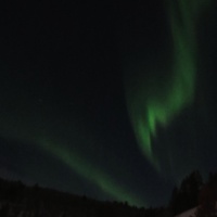
Geavu Wasteland, Lake Jorpa 
Finished ambiance light 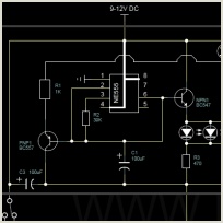
Schematics 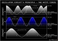
Principle of LED channels 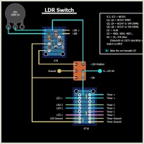
Veroboard version 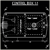
Drawings for control box 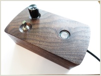
Walnut control box |
|
Feel free to post comments, questions or anykind of feedpack via form below. You can also send e-mail to: @ ffholm.com The form has been assembled with salvaged parts. It's rude but still works. |
 |
 |
 |
 |
|
|
PÄIVITYKSET (FIN)
Venttiileistä pyyhitty pölyjä 18/5/26 Taideaiheet päivitetty 15/4/18 Rakennusinsinöörien salatieteet päivitetty 15/4/18 Kaksoiskielinen sähkökannel 7/1/18 |
UPDATES (EN)
Aurora Borealis in a vodka bottle 9/11/14 Chili-terror: Pain in the arse 17/8/14 |
|
Fager-Fagerholm Prod since 2011 | |